It is already difficult to present modern electronics without chips. In order that even the most ordinary calculator could carry out calculations, in it chips with logical elements are used. They give the chance to perform logical operations of inversion, a disjunction and conjunction.
The binary logic is the basis for a computer system of calculations. It means that for carrying out all possible mathematical calculations only two numbers – 1 and 0 are used. Such system of calculations will seem to the person very inconvenient, but for the car it is the most optimum as allows to transform the most difficult calculations to operations with zero and unit. What, in turn, allows to achieve high speed of a system.
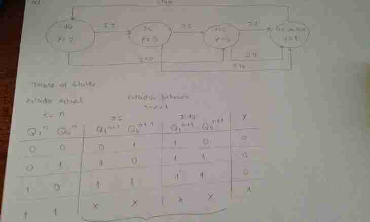
According to a binary numeral system, use only two logical variables – 1 and 0. Basic logical elements are schemes "I", "OR", "NOT", each of which performs one function.
Basic logical Element "I" realizes conjunction (logical multiplication) and works as follows. The logical element of a chip has three conclusions: two on an entrance and one at the exit. Logical unit (that is tension) appears at the exit only if tension is given on both entrances at once – on the first and on the second. That is if on both entrances 1, then and at the exit 1. If on entrances 0, at the exit 0. If on one (any) entrance 0, on another 1, at the exit is 0. Thus, logical unit appears at the exit only in one case from four. The logical ILI element realizes a disjunction (logical addition) and differs from previous only in logic. Logical unit appears at the exit in case logical 1 it is given on one of two entrances. That is on one or on another. In all other options at the exit there will be a logical zero, that is lack of output voltage on the corresponding conclusion of a chip. The logical NE element realizing inversion (denial) is very important. In it only two conclusions – one on an entrance and one at the exit. The logic of work is very simple: if on an entrance 0, at the exit 1. If on an entrance moves 1, at the exit 0 appears. Rub described above the main logical an element can form more difficult combinations – for example, "ILI-NE" when the signal at the exit is inverted, "YING" - here too is present inverting of a signal. Existence of various logical elements allowed developers of teach computers to carry out them necessary mathematical calculations.
