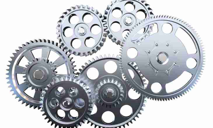
In mechanical engineering the mechanisms called gear transmissions are often used. Their basic purpose - transformation of rotary motion of a shaft to progress of a lath or transfer of rotary motion from one shaft to another. In such transfers a gear wheel usually call a cogwheel with smaller quantity of teeths.
It is required to you
- - the computer with the installed computer-aided engineering system;
- - drawing tools (curves, rulers, pencils) for implementation of the drawing on paper;
- - tracing-paper or paper;
- - the printer or the plotter for the printout of the drawing (if it is necessary).
Instruction
1. Pick up the material necessary for calculation of a gear wheel. For this purpose you will need the text of GOST 16532-70 on calculation of geometry of gear transmissions. It is possible to use other reference books, for example, special books by calculation of such transfers in which necessary formulas will be specified.
2. Find out basic data which will be required to you for implementation of the drawing of a gear wheel. As a rule, for creation of an initial contour of tooth and the image of a gear wheel such parameters as the module of a cogwheel and number of teeths are required. The sizes and a form of an initial contour of teeths have to correspond to GOST 13755-81.
3. Execute the drawing of a gear wheel, following the rules stated in GOST 2.403-75 and GOST 2.402-68. As a rule, happens one view with the put section enough. Do not forget that on the image of a gear wheel diameter of tops of teeths, width of a gear wreath, radiuses of rounding off or the sizes of facets for edges of teeths, roughness of side surfaces of teeths has to be specified. If at a gear wheel there are additional structural elements (grooves, openings, deepenings, etc.) which cannot be shown on one look, draw an auxiliary view.
4. Arrange on the drawing the table of parameters of a gear wreath of a gear wheel. The table has to consist of three parts which separate from each other the continuous main line. Specify basic data in the first part: module, number of teeths, normal initial contour, shift coefficient, degree of accuracy and type of interface. Give the image of an initial contour of tooth with necessary sizes if the parameters specified in the table are not enough for its definition. Enter data for control of mutual provision of heteronymic profiles of teeths in the second part of the table. Specify the dividing diameter of a gear wheel and the other help sizes in the third part of the table.
5. Do not forget to write the technical requirements necessary for production of a gear wheel. In the corresponding column specify material of which it will be made in the main inscription of the drawing.

