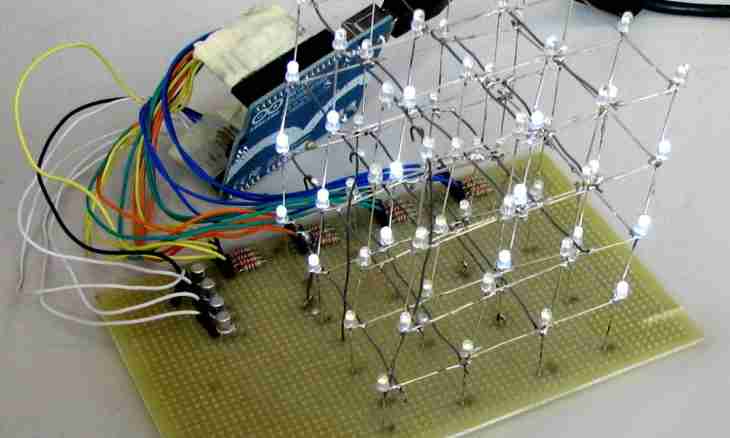
For the correct reading electric circuits it is necessary not only to know symbols of components, but also it is good to represent how they are formed in blocks. To understand features of interaction between elements of the electronic device, learn to define how according to the scheme there passes the signal and as it will be transformed.
Instruction
1. Begin acquaintance with the scheme with allocation of power-supply circuits. As a rule, places of giving of supply voltage on cascades of the device are located on the scheme from above. Food moves on loading, and then comes to the anode of the electron tube or to a collector chain of the transistor. Find an electrode junction with the corresponding conclusion of loading; in this place the strengthened signal is removed from a cascade.
2. Define entrance chains of each cascade. Allocate the basic control element of a cascade and study the auxiliary elements adjoining it.
3. Find the condensers located before an entrance of a cascade and at its exit. These elements play an important role in strengthening of alternating voltage. Condensers are not calculated on passing of a direct current therefore the entrance resistance of the following block will not be able to bring a cascade out of the stable mode on a direct current.
4. You pass to acquaintance with those cascades which are intended for strengthening of a signal on a direct current. The components forming tension connect without condensers here. The majority of similar cascades function in the analog mode.
5. Define the sequence of cascades to reveal the directions of passing of a signal. Pay special attention to converters of frequency and detectors. Find out what of cascades are connected consistently and what – a parallel image. At parallel connection of cascades several signals are processed independently one from another.
6. In addition to the schematic electric circuit study the scheme of connection (so-called wiring diagram) which is attached to it. Features of configuration of elements of the electronic device will help to understand what main units of a system. On the wiring diagram it is also simpler to define the central element of a system and interaction between it and auxiliary subsystems.
